HVDC Cable Installation
Overview of HVDC cable installation requirements during design of the route
High‑voltage direct current (HVDC) cable installations are unforgiving: excessive pulling tension or sidewall bearing pressure (SWBP) can damage conductor, screens, and insulation and shorten asset life.
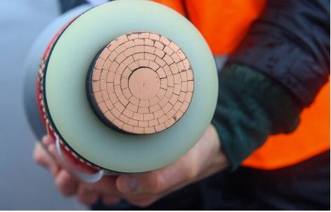
Generally, at least two cables are required for HVDC underground/subsea transmission, unless an earth/sea electrode is to be used at the converter stations, although it should be recognised there can be environmental issues with such a solution. In a monopolar scheme, these will consist of a heavily insulated HV cable and a lightly insulated return cable; whereas in bipolar designs both cables operate at high voltages and require heavy insulation.
The same principles and installation techniques for onshore underground AC cables apply to DC, with the exception that reactive compensation is not required for DC transmission and fewer cables are usually needed (minimum of two cables for DC rather than three for AC). As cables need to be spaced far apart to allow the heat generated to dissipate in the ground, a cable easement corridor of around 12m wide will be required for an HVDC route consisting of four cables, with increased width to account for section joints and access during construction and maintenance. This causes a significant environmental impact in construction and reinstatement and results in ‘land sterilisation’, as the cable corridor cannot be used for construction or certain types of agriculture.
Use manufacturer limits first. Where project-specific data is unavailable, typical industry guidance and recommended practice help define safe envelopes for tension, SWBP, bend radii, and coefficients of friction (CoF).
Why pulling calculations matter on HVDC
· • Asset integrity: Excess SWBP at bends and cumulative tension across long routes can crush or deform shields/insulation and initiate partial discharge mechanisms.
· • Design feasibility: Calculations determine maximum safe pulling lengths, need for intermediate assist points, and acceptable pull direction.
· • Compliance: HVDC standards emphasise robust design and station/cable integrity across DC grids and converter technologies.
Typical limits and parameters
· • Max pulling tension via conductor: Copper ≈ 5 kg/mm²; Aluminium ≈ 3 kg/mm²; many projects cap around 2 tonnes.
· • Coefficient of friction (f): 0.35–0.5 without lube; 0.14–0.2 for treated jackets.
· • SWBP: Manufacturer-specific; typical 500–1000 lb/ft (7.3–14.6 kN/m).
· • Bend radius: Respect minimum installation radius; larger radii reduce SWBP.
Planning tips that prevent failures
· • Get cable-specific limits first.
· • Measure your route and optimise pull direction.
· • Choose correct CoF based on lubricant and jacket.
· • Check SWBP per bend and adjust radii or assist points.
· • Verify jamming and clearance.
Need a second set of eyes on your pull plan? Request a design review via our Contact page.